
 EN
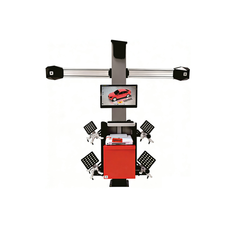
What a 3D wheel alignment machine is really measuring
A 3D wheel alignment machine does not measure angles directly. It measures where things are in space. Cameras mounted on a crossbeam or tower track targets clamped to the wheels. Each target carries reflective dots or a patterned face. The cameras record the target position and orientation, then software turns those coordinates into wheel plane geometry. From there come camber, toe, caster, SAI, thrust angle, and included angle. The numbers on the screen are the output. The input is a set of 3D coordinates captured many times per second.
Cameras, targets, and the math that connects them
The core principle is triangulation. Two or more cameras with a known separation view the same target. By comparing the images, the system calculates distance and angle to the target. Photogrammetry extends that idea: multiple known points on the target define a rigid body, and the software solves for its position and rotation in 3D space. That is why target placement matters. A loose clamp or a bent target face introduces error before any measurement begins. A wheel alignment machine with good optics still needs clean targets and stable mounting. Calibration is not optional. The camera-to-camera relationship must be known, and the reference plane must be established.
Building the vehicle coordinate system
Every alignment reading is relative to a reference. The machine first establishes a vehicle centerline or thrust line. Some systems use a rolling compensation procedure, where the vehicle is pushed forward and backward a short distance. Others use a steering procedure or a lift-based reference. The goal is the same: define where the vehicle actually sits, not where the rack assumes it sits. From that reference, individual wheel angles become meaningful. Toe is measured relative to the thrust line. Camber is measured against vertical. Caster and SAI require a steering sweep, because those angles describe the steering axis, not the wheel plane. The software watches target movement during the sweep and calculates the axis tilt.
Runout compensation and the errors it removes
Wheels are not perfect. A rim may have slight lateral or radial runout. The tire may not seat perfectly. When a target spins with the wheel, that runout makes the target appear to wobble. Without compensation, the system reads that wobble as a change in toe or camber. Runout compensation asks the operator to rotate the wheel or roll the vehicle so the software can map the eccentricity and subtract it. Skipping this step is one of the most common causes of repeatability problems. Two alignments on the same car can disagree if runout is handled differently. The procedure takes a few extra minutes. It saves comebacks.
| Measurement approach | Reference method | Typical strength | Common limitation |
|---|---|---|---|
| Traditional bubble or laser | Gravity and manual levels | Low cost, simple | Slow, operator dependent |
| CCD or infrared | Line-of-sight targets | Faster than manual | Sensitive to obstructions |
| 3D camera system | Photogrammetry and 3D coordinates | Rich data, rolling compensation | Needs calibration and clean targets |
A shop floor case that exposed the weak link
At a high-volume tire and service center in the Midwest, a 3D wheel alignment machine was producing readings that did not match road test complaints. Technicians aligned a vehicle to spec, yet the steering wheel sat off center. The machine passed calibration, targets were clean, and the clamps were tight. The problem turned out to be the floor. The alignment bay had a slope and a shallow dip near the front turn plates. During rolling compensation, the vehicle moved through that dip, and the software captured a slightly different reference each time. After the bay was leveled and the camera beam was rechecked, repeatability improved. The lesson was not that 3D systems are fragile. It was that a wheel alignment machine depends on its environment. SAE J670 defines many of the vehicle dynamics terms used in alignment work, including camber, toe, and caster. The definitions are precise. The physical setup must be just as precise.
Where 3D systems earn their cost and where they do not
3D alignment systems shine in shops that need speed, documentation, and repeatability. They show live readings, store before-and-after reports, and guide the technician through adjustments. They handle a wide range of vehicles without swapping adapters for every make. The limits are real. A 3D system cannot fix a bent strut, a worn tie rod, or a damaged subframe. It cannot compensate for a misloaded vehicle or incorrect tire pressure. It needs a stable power supply, a clean optical path, and a reasonably level bay. In a home garage with a perfectly flat floor and occasional use, a simpler system may be enough. In a busy commercial bay, the 3D approach usually pays back through fewer comebacks and better records. The same discipline applies to the equipment supply chain. CAVALRY has built its reputation on manufacturing control, quality inspection, and global support for automotive equipment, with more than two decades of development behind its product line. A wheel alignment machine is only as good as the process around it, and that process starts with dependable hardware and clear support.